Difference between revisions of "DIN Rail LED-Dimmer"
From InCircuit
| Line 3: | Line 3: | ||
== Hardware == | == Hardware == | ||
| − | '''{{PAGENAME}}''' - 8 | + | '''{{PAGENAME}}''' - 8 Channel LED-Dimmer Module |
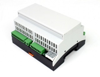
[[File:DIN Rail LED-Dimmer.jpg |320px | thumb | right | {{PAGENAME}}]] | [[File:DIN Rail LED-Dimmer.jpg |320px | thumb | right | {{PAGENAME}}]] | ||
| Line 10: | Line 10: | ||
*8x LED dimmer output | *8x LED dimmer output | ||
| − | *Intensity is variable in | + | *Intensity is variable in 12 steps or steplessly |
*8x Binary input for external switches | *8x Binary input for external switches | ||
*2x Relais output (COM, NO) switching power: 230V/5A | *2x Relais output (COM, NO) switching power: 230V/5A | ||
| Line 21: | Line 21: | ||
*Other DIN-Rail modules available | *Other DIN-Rail modules available | ||
*Input voltage: 24V DC | *Input voltage: 24V DC | ||
| − | * | + | *Temperature range from -10°C to +70°C |
<!-- | <!-- | ||
| Line 29: | Line 29: | ||
== Railbus Registers / Sub addresses == | == Railbus Registers / Sub addresses == | ||
| − | Communicating via the [[DIN Rail BUS Protocol]], | + | Communicating via the [[DIN Rail BUS Protocol]], device is fully controlable through these registers: |
| Line 70: | Line 70: | ||
|} | |} | ||
| − | |||
| − | |||
| − | |||
| − | |||
| − | |||
| − | |||
== Downloads == | == Downloads == | ||
Revision as of 15:16, 12 November 2013
Hardware
DIN Rail LED-Dimmer - 8 Channel LED-Dimmer Module
Features:
- 8x LED dimmer output
- Intensity is variable in 12 steps or steplessly
- 8x Binary input for external switches
- 2x Relais output (COM, NO) switching power: 230V/5A
- 1x RS485 via BUS connector
- Numeric display for device address
- Arbitrary number of modules mountable side by side
- Easy connection of all modules with BUS connector
- All modules can communicate via RS485
- DIN-Rail enclosure: 6 pitch units (div)
- Other DIN-Rail modules available
- Input voltage: 24V DC
- Temperature range from -10°C to +70°C
Railbus Registers / Sub addresses
Communicating via the DIN Rail BUS Protocol, device is fully controlable through these registers:
| SADR | 31 - 22 | 21 - 16 | 15 - 6 | 5 - 0 | |
|---|---|---|---|---|---|
| 0 | 0 | DIGIN | 0 | RELAIS | R |
| 0 | 0 | 0 | 0 | RELAIS | W |
| 1 | 0 | DIGIN | 0 | RELAIS | R |
| 1 | 0 | 0 | 0 | RELAIS | W |
Downloads
