Difference between revisions of "DIN Rail PWM-Driver"
From InCircuit
| Line 20: | Line 20: | ||
*Input voltage: 24V DC | *Input voltage: 24V DC | ||
*Tempearture range from -10°C to +70°C | *Tempearture range from -10°C to +70°C | ||
| + | |||
| + | |||
<!-- | <!-- | ||
Revision as of 16:58, 12 November 2013
Hardware
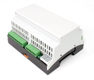
DIN Rail PWM-Driver - 15 Chanel PWM-Driver Module
Features:
- 15x PWM-Driver output
- 8x Binary input for external switches
- 1x RS485 via BUS connector
- Numeric display for device address
- Arbitrary number of modules mountable side by side
- Easy connection of all modules with BUS connector
- All modules can communicate via RS485
- DIN-Rail enclosure: 6 pitch units (div)
- Other DIN-Rail modules available
- Input voltage: 24V DC
- Tempearture range from -10°C to +70°C
Railbus Registers / Sub addresses
Communicating via the DIN Rail BUS Protocol, the DIN Rail PWM-Driver implements two registers. Both registers have the same layout:
| SADR | 31 - 22 | 21 - 16 | 15 - 6 | 5 - 0 | |
|---|---|---|---|---|---|
| 0 | 0 | DIGIN | 0 | RELAIS | R |
| 0 | 0 | 0 | 0 | RELAIS | W |
| 1 | 0 | DIGIN | 0 | RELAIS | R |
| 1 | 0 | 0 | 0 | RELAIS | W |
On reading, the current status of all Pins is transmitted. If the first relais is on, bit 0 is set. If the second relais is on, bit 1 is set, and so on.
On writing only the 6 lowest bits are interpreted, and the relais set accordingly.
Writing to SADR 0 sets the relais only temporary. After a power-cycle all relais will be set to their initial state. This can be set by writing to SADR 1. In this case the state is set and stored in EEProm.
Downloads
