ICflyDisplay
General Information

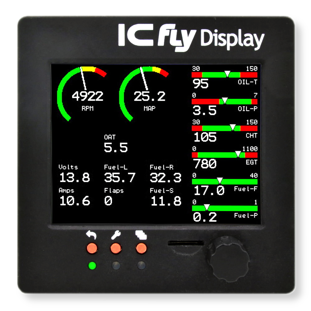
Flexible flight instrument for fixed installation
The ICflyDisplay brings the artificial horizon of the ICflyAHRSII into the cockpit. The sunlight-readable touchscreen guarantees a clear representation even in direct sunlight, as well as a simple usability. All settings are configurable via an intuitive menu operated by a high-feedback rotary encoder.
The device mode can be selected within the integrated setup menu:
- Horizon with pressure, position and speed data are displayed in real time
- Motor data display for the Rotax 912, (compatible with ICflyMotorbox 912)
The ICflyDisplay has 2 ICflyBus connectors that supply operating voltage and horizon- / motordata. It can be added to an existing ICfly-System easily. It is possible to operate two or more devices in a row on the same bus.
Features
- Artificial horizon (requires ICflyAHRSII)
- Motor data display (ICflyMotorbox912 needed)
- Traffic data display (requires Traffic Sensor)
- ICflyBus: wired connection between ICfly devices (ICflyAHRSII, ICflyDisplay, ICflyMotorbox 912 and more)
- Sunlight-readable display: clear presentation even in direct sunlight
- Integrated Touchscreen & rotary encoder: configuration and selection of the operating mode directly on the device
- Fixed installation: mounting in 80mm standard instrument cutout
- Low power consumption of only 1.2 W
Device Configuration
The ICflyDisplay can be either configured using the internal menu or by several configuration files on the microSD-card. Up to now the ICflyDisplay supports the following configuration files.
| Config-file | editable values |
|---|---|
| Airspeed.txt | airspeed-limits displayed in the artificial horizon view |
| Datachannel.txt | serial interface's speeds and serial data source for horizon and motor view |
| General.txt | QNH-value, brightness and start-window |
| Motorview.txt | types, values and positions of the instruments of the motor view |
| Units.txt | units of airspeed, altitude and vario |
| Traffic.txt | warning settings and view orientation |
Configuration Files
The features described in this chapter are available since firmware version 1.00.
As soon as the ICflyDisplay has been started once, with microSD-card inserted, initial configuration files are stored on the card. To modify the files, remove the microSD-card from the ICflyDisplay and open the files with a text-editor on a computer. The card-socket is a push & push type. So to remove the card, you have to push it inwards first. The microSD-card should contain the config-files mentioned above. Their structure and influence on the configuration of the ICflyDisplay is described below.
Airspeed
The Airspeed.txt file looks like this:
# this is a comment # comment lines and empty lines will be ignored # please do not insert any Spaces or tabs in the Settingline ######################################################################################### # HorizonView Speedlimits [1/100 knots] # example: 77.0 km/h = 41,57 knots * 1.852 # example: 41,57 knots = 77.0 km/h / 1.852 -> 4157 [1/100 knots] Vs0;4157; Vfe;6749; Vs1;5345; Vno;12688; Vne;15118; Va;8909;
It contains the aircraft's speed limits. Editing the values in this file results in changing the speed limits displayed in the horizon view. Refer to the Datasheet for more information about the speed limits
Datachannel
The Datachannel.txt file looks like this:
# this is a comment # comment lines and empty lines will be ignored # please do not insert any Spaces or tabs in the Settingline ######################################################################################### # baudrate for Datastream # possible values are: 1200, 4800, 9600, 19200, 38400, 57600, 115200, 230400, 256000 Up1;230400; Up2;230400; Dwn1;230400; Dwn2;230400; ######################################################################################### # source for View # possible values are: # 1 = Up1 -> Upstream RX1/TX1 on female D-SUB15 # 2 = Up2 -> Upstream RX2/TX2 on female D-SUB15 # 3 = Dwn1 -> Downstream RX1/TX1 on male D-SUB15 # 4 = Dwn2 -> Downstream RX2/TX2 on male D-SUB15 DatastreamHorizon;1; DatastreamMotorview;2; DatastreamTrafficview;3;
It contains all settings of the serial interfaces of the ICflyDisplay. Editing the values in the upper half of the file changes the baud rates of the serial interfaces. The lower half of the file selects the data sources for horizon-/ motor- and traffic-view. The displayed configuration sets all baud rates to 230400, the sources for horizon-/ motor- and traffic-data to Up1 / Up2 and Dwn1. Please notice, that only the listed values are valid.
General
The General.txt file looks like this:
# this is a comment # comment lines and empty lines will be ignored # please do not insert any Spaces or tabs in the Settingline ######################################################################################### # QNH QNH;1013; ######################################################################################### # Brightness in % # possible values are: 10, 20, 30, 40, 50, 60, 70, 80, 90, 100 Brightness;100; ######################################################################################### # Start Window # 0 = Horizon View # 1 = Motor View # 2 = Traffic View DisplayMode;0; ######################################################################################### # Enable Views # 0 = View disabled # 1 = View enabled HorizonViewEnable;1; MotorViewEnable;1; TrafficViewEnable;1;
It contains all general settings of the ICflyDisplay. Here the QNH-value, the display-brightness and the start window can be modified. Start Window means the mode, the display starts operating in (0 -> horizon view, 1 -> motor view, etc.). You can enable/disable certain Views with Enable Views (0 -> View disabled, 1 -> View enabled).
MotorView
The MotorView.txt file looks like this:
# this is a comment # comment lines and empty lines will be ignored # please do not insert any Spaces or tabs in the Settingline ######################################################################################### # the LCD Display has 320x/240y pixel # # y-direction # ^ # 240 pixel | # +---------> x-direction # 320 pixel ######################################################################################### # type 1: basic Instrument # possible names are: FuelLeft, FuelRight, FuelSum, Amps, AmbientTemp, Volts, Flaps # size of this Element is 40x/30y pixel # type; name; visible; position x; position y; min value green; max value green; red LED on if outside green # 1;FuelLeft;1;80;0;5.0;60.0;1; 1;FuelLeft;1;80;0;5.0;60.0;1; # 1;FuelRight;1;150;0;5.0;60.0;1; 1;FuelRight;1;150;0;5.0;60.0;1; # 1;FuelSum;0;150;25;-1.0;1000.0;1; 1;FuelSum;0;150;25;-1.0;1000.0;1; # 1;Amps;0;10;25;-5.0;15.0;1; 1;Amps;0;10;25;-5.0;15.0;1; # 1;AmbientTemp;1;10;50;-40.0;100.0;1; 1;AmbientTemp;1;10;50;-40.0;100.0;1; # 1;Volts;1;10;0;11.5;15.0;1; 1;Volts;1;10;0;11.5;15.0;1; # 1;Flaps;0;80;25;-50.0;50.0;1; 1;Flaps;0;80;25;-50.0;50.0;1; ######################################################################################### # type 2: Progressbar # possible names are: OilTemp, OilPressure, Cyl1Temp, Cyl2Temp, Egt1Temp, Egt2Temp, FuelFlow, FuelPress # size of this Element is 110x/40y pixel # type; name; visible; position x; position y; min value scala; max value scala; min value green; max value green; red LED on if outside green # 2;OilTemp;1;210;160;30.0;130.0;50.0;110.0;1; 2;OilTemp;1;210;160;30.0;130.0;50.0;110.0;1; # 2;OilPressure;1;210;200;0.0;7.0;2.0;5.0;1; 2;OilPressure;1;210;200;0.0;7.0;2.0;5.0;1; # 2;Cyl1Temp;1;210;120;30.0;120.0;60.0;110.0;1; 2;Cyl1Temp;1;210;120;30.0;120.0;60.0;110.0;1; # 2;Cyl2Temp;1;210;80;30.0;120.0;60.0;110.0;1; 2;Cyl2Temp;1;210;80;30.0;120.0;60.0;110.0;1; # 2;Egt1Temp;0;210;80;0.0;1100.0;100.0;900.0;1; 2;Egt1Temp;0;210;80;0.0;1100.0;100.0;900.0;1; # 2;Egt2Temp;0;210;0;0.0;1100.0;0.0;700.0;1; 2;Egt2Temp;0;210;0;0.0;1100.0;0.0;700.0;1; # 2;FuelFlow;1;210;0;0.0;40.0;0.0;40.0;0; 2;FuelFlow;1;210;0;0.0;40.0;0.0;40.0;0; # 2;FuelPress;1;210;40;0.0;1.0;0.0;1.0;1; 2;FuelPress;1;210;40;0.0;1.0;0.0;1.0;1; ######################################################################################### # type 3: round Instrument # possible names are: RPM, MAP # size of this Element is 100x/100y pixel # type; name; visible; position x; position y; min value scala; max value scala; start value yellow; start value red; red LED on if in red # 3;RPM;1;5;140;1000.0;6500.0;5500.0;5800.0;1; 3;RPM;1;5;140;1000.0;6500.0;5500.0;5800.0;1; # 3;MAP;1;100;140;10.0;32.0;28.0;30.0;1; 3;MAP;1;100;140;10.0;32.0;28.0;30.0;1;
This file defines the layout of the motor-data display. Every instrument of the motor-data display is defined in this file. There are 3 different types of instruments:
| Type | Appearance | Size in pixels (x/y) | generated by | Used for |
|---|---|---|---|---|
| type 1: basic instruments |  | 40/30 | t;n;v;px;py;ming;maxg;redLED | fuel-level & -flow, battery-voltage & -current, ambient temperature, flaps |
| type 2: progress bars |  | 110/40 | t;n;v;px;py;mins;maxs;ming;maxg;redLED | oil-temperature & -pressure, cylinder head temperature, exhaust gas temperature, fuel-flow & -pressure |
| type 3: round instruments |  | 100/100 | t;n;v;px;py;mins;maxs;starty;startr;redLED | RPM, MAP (manifold pressure) |
Every Instrument is generated by one line of definitions in the config-file. Every line consists of semicolon-separated values without space characters. Refer to the column generated by in the table above to see the structure needed for each type of instrument. The abbreviations stand for the following:
| Abbreviation | Meaning |
|---|---|
| t | type of the instrument; 1 -> basic, 2 -> progress bar, 3 -> round |
| n | name of the instrument; only the given possible names for the corresponding type are allowed |
| v | visibility of the instrument; 1 -> visible, 0 -> not visible |
| px | position of the instrument in x-direction |
| py | position of the instrument in y-direction |
| ming | minimum value of the green region of the instrument (only type 1&2, red below this value) |
| maxg | maximum value of the green region of the instrument (only type 1&2, red above this value) |
| mins | minimum value of the scale (only type 2&3) |
| maxs | maximum value of the scale (only type 2&3) |
| starty | start value of the yellow region (only type 3, green region below this value) |
| startr | start value of the red region (only type 3, yellow region below this value) |
| redLED | switch on red LED if value leaves the green region; 1 -> yes, 0 -> no |
Normally you do not have to define instruments by yourself. The MotorView.txt-file contains one instrument for every data channel of the ICflyMotorbox 912. Some instruments are just set invisible. To personalize the motor view, simply make the required instruments visible by setting their v-value to 1 and place them in the desired location on the screen by setting the px- and py-values accordingly. The origin (0/0) of the coordinate system is located in the lower left corner of the screen.
Units
The Units.txt file looks like this:
# this is a comment # comment lines and empty lines will be ignored # please do not insert any Spaces or tabs in the Settingline ######################################################################################### # Airspeed Unit # 0 = km/h # 1 = knots HorizonAirspeed;0; TrafficAirspeed;0; ######################################################################################### # Altitude Unit # 0 = ft # 1 = m HorizonAltitude;0; TrafficAltitude;0; ######################################################################################### # Vario Unit # 0 = ft/min # 1 = m/s HorizonVario;1; ######################################################################################### # Distance Unit # 0 = km # 1 = Nm TrafficDistance;0;
It allows changing the units of airspeed, altitude, vario and distance in the horizon- and traffic-view:
- Airspeed; 0 -> km/h, 1 -> knots
- Altitude; 0 -> ft, 1 -> m
- Vario; 0 -> ft/min, 1 -> m/s
- Distance; 0 -> km, 1 -> Nm
Traffic
The Traffic.txt file looks like this:
# this is a comment # comment lines and empty lines will be ignored # please do not insert any Spaces or tabs in the Settingline ######################################################################################### # Safe Range in [m/1000] SafeRange;500000; SafeAltitude;100000; ######################################################################################### # View orientation # 0 = based on own heading # 1 = based on north TrafficOri;0;
It allows changing the distance where the Display shows a warning. The warning zone is a cylinder with radius SafeRange and height 2x SafeAltitude.
- SafeRange; 500000 -> 500 m
- SafeAltitude; 100000 -> 100m
Firmwareupdate
Please refer to the datasheet - Section 9: "Firmwareupdate via SD-Card" for instructions.
The firmware of the ICflyDisplay can be updated via SD-Card. This functionality is available since firmware version 1.01.
Please refer to the table below for all available firmware-updates.
| Firmwareversion | Description | Downloadlink |
|---|---|---|
| 1.04 | improved artificial horizon support for replacement LCD screen Bug fixes | Download |
| 1.02 | Bug fixes | Download |
| 1.01 | Add Traffic View Device Configuration through Files | Download |