SpiderR40ESP32C3
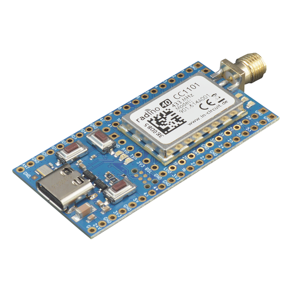
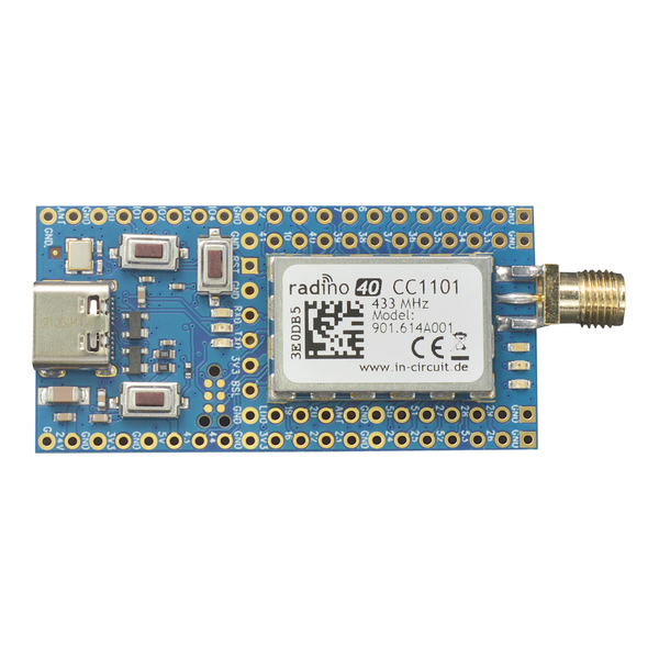
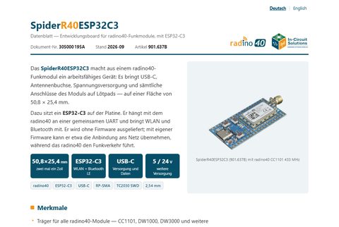
The SpiderR40ESP32C3 turns a radino40 radio module into a working device: USB-C, antenna socket, power supply and all connections of the module on solder pads – on 50.8 × 25.4 mm.
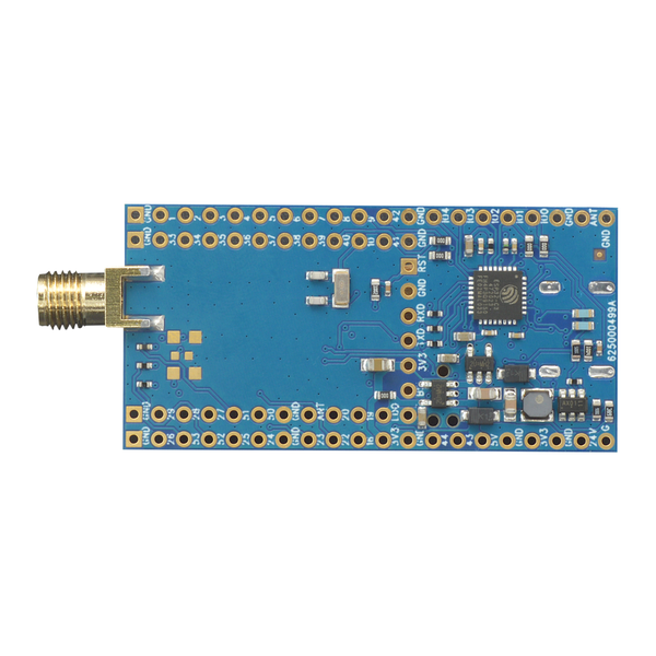
An ESP32-C3 sits on the bottom side. It shares a UART with the radino40 and adds WiFi and Bluetooth. It is delivered without firmware; with firmware of your own it can handle the network connection, for instance, while the radino40 handles the radio traffic.
Hardware
Features
- Carrier for all radino40 modules – CC1101, DW1000, DW3000 and others
- ESP32-C3FH4 with 4 MB flash, WiFi and Bluetooth LE
- USB-C for power, programming and serial connection – one data pair per chip, the plug orientation selects the chip
- RP-SMA antenna socket for the radino40
- All connections of the radino40 on solder pads, 2.54 mm pitch
- Five free connections of the ESP32-C3 (IO0 to IO4)
- Power from USB-C, 5 V or 24 V
- Buttons for reset and bootloader, three LEDs
- 50.8 × 25.4 × 3.5 mm, 12 g
USB-C: the plug orientation selects the chip
The USB-C socket carries two data pairs: A6/A7 go to the radino40 (nRF52840), B6/B7 to the ESP32-C3. A USB cable connects only one of these pairs to the computer. Which chip appears on the computer therefore depends on the orientation of the plug; flip the plug and the other chip appears. Power works in both orientations.
| Chip | Appears on the computer as |
|---|---|
| radino40 in the bootloader | USB device "Open DFU Bootloader", ID 1915:521F, serial port (COM port) |
| radino40 running an application | USB ID 1DA9:0042, serial port |
| ESP32-C3 | USB ID 303A:1001 (USB Serial/JTAG of the ESP32-C3) |
To find the orientation, plug the cable in and check the device manager to see which chip appears. An ESP32-C3 without firmware normally connects and disconnects over and over; with Boot and Reset pressed together it stays visible. Label the cable afterwards (for example "ESP") and you no longer have to try.
Power supply
Three ways lead to the supply; they do not exclude each other, the inputs are decoupled by Schottky diodes:
| Input | Meaning |
|---|---|
| USB-C | 5 V from computer or power supply |
Pad 5V | 5 V for installation in a device |
Pad 24V | a step-down converter (AOZ1280CI) derives 5 V from it |
A linear regulator generates 3.3 V for radino40 and ESP32-C3 from the 5 V;
it supplies up to 600 mA. The same voltage is available on pad 3V3 for
your own circuitry.
Pad assignment
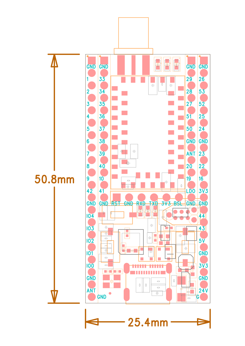
The numbers are the pin numbers of the radino40 and are printed that way on the board; the Signal column names the corresponding pin of the nRF52840 inside the module. IO0 to IO4 belong to the ESP32-C3.
Two pads are labelled ANT and mean different things: the left one the antenna of the ESP32-C3, the right inner one the Bluetooth antenna of the radino40.
Left row, outer
| Pad | Signal | Meaning |
|---|---|---|
| GND | Ground | |
| 1 | P0.17 | GPIO |
| 2 | P0.15 | GPIO |
| 3 | P0.14 | GPIO |
| 4 | P0.12 | GPIO; Trace buffer TRACEDATA[1] |
| 5 | P0.07 | GPIO; Trace buffer clock |
| 6 | P0.03 | GPIO (low-freq.); Analog input |
| 7 | P0.05 | GPIO; Analog input |
| 8 | P0.29 | GPIO (low-freq.); Analog input |
| 9 | P0.31 | GPIO (low-freq.); Analog input |
| 42 | P0.27 | GPIO |
| GND | Ground | |
| IO4 | GPIO4 | free connection of the ESP32-C3 |
| IO3 | GPIO3 | free connection of the ESP32-C3 |
| IO2 | GPIO2 | free connection of the ESP32-C3 |
| IO1 | GPIO1 | free connection of the ESP32-C3 |
| IO0 | GPIO0 | free connection of the ESP32-C3 |
| GND | Ground | |
| ANT | Antenna of the ESP32-C3 (WiFi, Bluetooth LE) | |
| GND | Ground |
Left row, inner
| Pad | Signal | Meaning |
|---|---|---|
| GND | Ground | |
| 33 | P0.16 | GPIO |
| 34 | P1.08 | GPIO |
| 35 | P1.10 | GPIO |
| 36 | P0.11 | GPIO |
| 37 | P0.02 | GPIO (low-freq.); Analog input |
| 38 | P0.04 | GPIO; Analog input |
| 39 | P0.28 | GPIO (low-freq.); Analog input |
| 40 | P0.30 | GPIO (low-freq.); Analog input |
| 10 | P0.01 | GPIO; Analog input; Connection for 32.768 kHz crystal |
| 41 | P0.00 | GPIO; Analog input; Connection for 32.768 kHz crystal |
| GND | Ground |
Bottom row
| Pad | Signal | Meaning |
|---|---|---|
| RST | Reset | Reset of the radino40 – GPIO; nRF52840 reset |
| GND | Ground | |
| RXD | P0.06 | serial interface to the ESP32-C3 – GPIO; (RXD) |
| TXD | P0.08 | serial interface to the ESP32-C3 – GPIO; (TXD) |
| 3V3 | 3.3 V, supply of the radino40 | |
| BSL | P0.13/BSL | Bootloader of the radino40 – GPIO (internal 1k pull-down) |
Right row, inner
| Pad | Signal | Meaning |
|---|---|---|
| GND | Ground | |
| 29 | P1.13 | GPIO (low-freq.) |
| 28 | P1.14 | GPIO (low-freq.) |
| 27 | P1.15 | GPIO (low-freq.) |
| 51 | P1.02 | GPIO (low-freq.) |
| 50 | P1.11 | GPIO (low-freq.); Trace buffer TRACEDATA[2] |
| GND | Ground | |
| ANT | Antenna of the radino40 (Bluetooth LE) | |
| 20 | P0.10 | GPIO (low-freq.); NFC antenna input |
| 19 | P0.09 | GPIO (low-freq.); NFC antenna input |
| LDO | Output of the linear regulator | |
| GND | Ground |
Right row, outer
| Pad | Signal | Meaning |
|---|---|---|
| GND | Ground | |
| 26 | P1.00 | GPIO (low-freq.); Trace buffer TRACEDATA[0], SWO |
| 53 | P1.06 | GPIO (low-freq.) |
| 52 | P1.04 | GPIO (low-freq.) |
| 25 | P1.01 | GPIO (low-freq.) |
| 24 | P1.03 | GPIO (low-freq.) |
| GND | Ground | |
| 23 | P1.05 | GPIO (low-freq.) |
| 22 | P1.07 | GPIO (low-freq.) |
| 16 | P0.13/BSL | Bootloader of the radino40 – GPIO (internal 1k pull-down) |
| 3V3 | 3.3 V, supply of the radino40 | |
| GND | Ground | |
| 44 | P1.09 | GPIO; Trace buffer TRACEDATA[3] |
| 43 | P0.26 | GPIO |
| 5V | 5 V – input or output | |
| GND | Ground | |
| 3V3 | 3.3 V of the board | |
| GND | Ground | |
| 24V | 24 V input of the step-down converter | |
| GND | Ground |
Programming connector TC2030 (SWD)
| Pad | Signal | Meaning |
|---|---|---|
| 1 | 3V3 | 3.3 V, supply of the radino40 |
| 2 | SWDIO | SWD data of the radino40 |
| 3 | Reset | Reset of the radino40 – GPIO; nRF52840 reset |
| 4 | SWCLK | SWD clock of the radino40 |
| 5 | GND | Ground |
| 6 | P1.00 | GPIO (low-freq.); Trace buffer TRACEDATA[0], SWO |
The ESP32-C3 inside
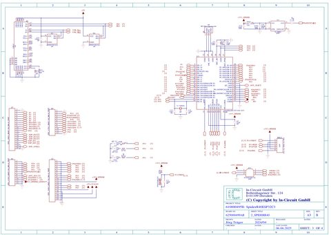
| ESP32-C3 | connected to | Meaning |
|---|---|---|
| GPIO21 | P13/RXD | serial interface to the radino40 (receive) |
| GPIO20 | P14/TXD | serial interface to the radino40 (transmit) |
| GPIO8 | P11/NRST | reset of the radino40 |
| GPIO10 | P16/BSL | bootloader of the radino40 |
| GPIO9 | ESP_BSLN | bootloader of the ESP32-C3 (button) |
| GPIO6 | LED_RD | LED red |
| GPIO7 | LED_GR | LED green |
| GPIO5 | LED_BL | LED blue |
| GPIO18 | USB_D- | USB-C (B7) |
| GPIO19 | USB_D+ | USB-C (B6) |
Assembly variants
The board is supplied with the radino40 soldered on. Which module it carries determines the radio technology:
| Part no. | radino40 fitted | Module | For |
|---|---|---|---|
| 901.637B | radino40 CC1101 433 MHz | 901.614A001 | narrowband, long range |
| 901.637B002 | radino40 CC1101 868 MHz | 901.614 | narrowband, SRD band |
| 901.637B001 | radino40 DW1000 | 901.528 | ultra-wideband, positioning |
| 901.637B004 | radino40 DW1000 with TCXO | 901.528A001 | ultra-wideband, tighter frequency tolerance |
| 901.637B003 | radino40 DW3000 | 901.620C | ultra-wideband, FiRa |
| 901.637 | none (bare board) | – | fit the module yourself |
Software
The radino40 is delivered programmed; it appears on the computer through its own USB interface (see USB-C). For the radino40 the tools and libraries of the radino40 range apply unchanged – see radino40 Software.
The ESP32-C3 is delivered without firmware. It has its own USB connection on the USB-C socket; for firmware of your own, choose the plug orientation of the ESP32-C3 and put it into its bootloader with the Boot and Reset buttons.
Downloads
See also
- radino40 – the module range
- radino40 Software – toolchain and libraries
- radino40 Spider RP-SMA – carrier board without ESP32
- radino40 Programmer