ICPROX-N

ICPROX-N is the stationary half of the ICPROX collision protection system: the infrastructure in the building. Modules mounted at junctions, gates and hazardous locations detect vehicles within an adjustable radius by ultra-wideband radio and react immediately — with a beacon, a horn or a barrier on site, and with a reduction request to the vehicle itself.
There is never a cable between building and vehicle. Each module runs on its own 24 V supply and is configured with slide switches alone — no PC, no software, no central system.
Core device 902.199B — Shop — System description
Features
- Danger points (spots) act locally: a vehicle entering the radius is slowed down and is free again once it leaves
- Gates act permanently: passing through hands the vehicle a zone it keeps until the next gate
- Detection radius adjustable on the device, 1.5 m to 19 m
- Device groups separate types of traffic from one another
- Set up with slide switches — no PC, no software
- Retrofittable without any work on the vehicle — the modules operate on their own
Components
| Component | Part no. | Task within ICPROX-N | Manual |
|---|---|---|---|
| ICPROX-4R2I | 902.199B | The core device: four relays, two inputs, indicator strip. Works as a danger point (SPOT), zone transition (GATE), vehicle unit (TAG) or in cable operation (EXTRA) | Manual · Switch configuration aid |
| ICPROX-ANT | 902.218 | On the device line of a control unit it links an ICPROX-P vehicle to the danger points and gates | Manual |
| ICPROX-SEC | 902.206 | Access control by RFID card — on the vehicle or stationary at a door | Manual |
SPOT and GATE — two ways to secure a place
The same device operates in two modes. Which one applies follows from the geometry of the danger point.
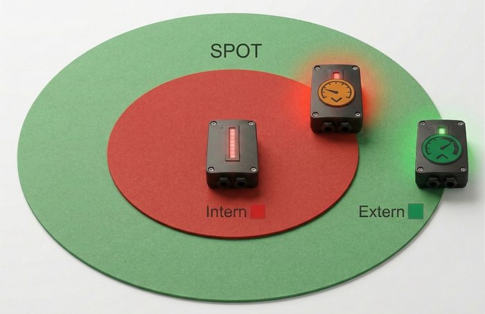
SPOT forms a circle around the mounting position. A vehicle is reduced while it remains inside the radius and continues unchanged once it leaves. The mode suits danger points with a centre: intersections, narrow passages, workstations. The radius is set on the device, from 1.5 to 19 metres.
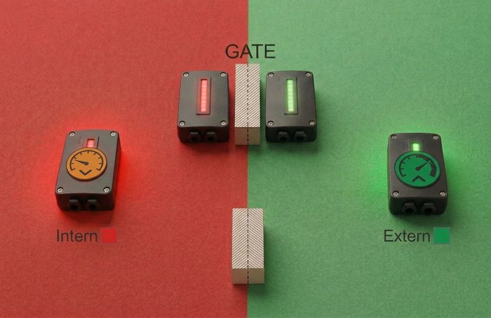
GATE forms no circle but a threshold between two zones. One device stands on each side; the vehicle stores which threshold it last crossed and in which direction. The restriction of the inner zone therefore remains in force regardless of the distance to the device. The mode suits zone boundaries: hall doors, workshops, outdoor yards.
The difference lies in how long the effect lasts: SPOT applies while the vehicle is inside the radius; GATE applies from crossing the threshold until it is crossed in the opposite direction.
Both are set with slide switches on the device — no PC, no software.
How a vehicle takes part
| Vehicle equipment | Link to ICPROX-N |
|---|---|
| ICPROX-4R2I as vehicle unit (TAG mode) | Receives the requests from the danger points directly by radio and carries them out through its own relays — no further devices on the vehicle |
| ICPROX-P system (control unit, display, antennas) | One additional ICPROX-ANT on the device line links the control unit to the infrastructure; the display shows danger points and the current zone |
Note: an ICPROX-P system joins the infrastructure later by simply adding one more antenna, whereas a 4R2I used as a vehicle unit cannot be reused when upgrading to the full system. The infrastructure itself is unaffected by the choice and works with either approach.
Getting started
- Identify the hazards: junctions, gates, racking aisles and exits first.
- Mount a module at each danger point, supply it with 24 V and wire the local beacon, horn or barrier through an interposing relay.
- Set the operating mode and detection radius on the slide switches; power off briefly after every change.
- A gate always needs two modules — one per side, each carrying the zone number of its side, both in the same device group.
- Equip the vehicles that are to react, then walk each danger point with a tag and check the switching points.
Operating modes, every switch combination and troubleshooting are described in full in the system description and in the ICPROX-4R2I manual.
Technical data
| Property | Value |
|---|---|
| Locating method | Ultra-wideband (UWB), 6.5 GHz |
| Detection radius | 1.5 m – 19 m, set on the device |
| Operating modes | SPOT, GATE, TAG, EXTRA |
| Relays / inputs | 4 volt-free relays, 2 digital inputs (24 V) |
| Zones | 4 gate levels (0–3) |
| Device groups | 4 (0–3) |
| Power supply | 8–24 V DC |
| Dimensions (L × W × H) | 130 × 76 × 35 mm |
| Weight | 80 g |
| Material | PA12 |
| Colour | black |
Caution: the relay contacts must only switch extra-low-voltage loads. Mains-powered beacons, horns, barriers or gate drives have to be driven through an interposing relay or contactor.
Downloads
- System description (HTML, English/German)
- Switch configuration aid
- Complete ICPROX manual (PDF, English)
- Gesamthandbuch (PDF, deutsch)