ICPROX-P

ICPROX-P is the vehicle-mounted half of the ICPROX collision protection system. Antennas on the vehicle continuously measure the distance to every tag around it — worn by people, fitted to other vehicles or to AGVs. From distance and direction the control unit derives a reduction level and applies it through its relays: warn, slow down, stop. No camera, no line of sight required.
ICPROX-P detects people. That is the decisive difference from an infrastructure-only installation with ICPROX-4R2I modules, which reacts to danger points and gates but not to a person crossing the aisle.
Sets 902.225 · 902.228 · 902.229 — Shop — System description
Features
- Detects people, AGVs and other vehicles carrying a tag
- One antenna for distance, three antennas for distance and direction
- Three adjustable reduction levels per vehicle
- Touch display with a map of the surroundings and a proximity tone
- Configured entirely through the control unit's web interface
- Joins the ICPROX-N infrastructure later by adding one more antenna
Components
| Component | Part no. | Task within ICPROX-P | Manual |
|---|---|---|---|
| ICPROX-CPU | 902.220 | Control unit: evaluates all measurements, switches four relays, provides the web interface | Manual |
| ICPROX-ANT | 902.218 | UWB antenna, 1–3 for locating, optionally one more for the building link | Manual |
| ICPROX-Tag | 902.214 | The wearable tag the vehicle detects in the first place | Manual |
| ICPROX-Display | 902.217 | Touch display with surroundings map and proximity tone | Manual |
| ICPROX-SEC | 902.206 | RFID access control, releases the vehicle for authorised drivers | Manual |
| ICPROX-KEY | 902.230 | Configuration key enabling the web interface | Manual |
One antenna or three?
| Configuration | What the vehicle detects | Typical use |
|---|---|---|
| 1 antenna | Distance to every tag, but not the direction | Vehicles with one clear main direction of travel |
| 3 antennas | Distance and direction; reduction can be tied to areas around the vehicle | All-round protection, narrow aisles, frequent manoeuvring |
| + 1 antenna on the device line | Additionally the danger points, gates and zones of ICPROX-N | As soon as the building is equipped |
Going from one antenna to three, and the step into the building, are pure extensions — control unit, display and tags stay the same.
What the driver sees
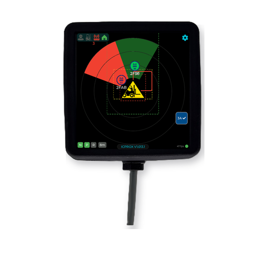
The display shows the surroundings from above, with the vehicle itself in the middle. How much of it is visible depends on how many antennas are fitted — with one antenna the system knows only the distance, with three it also knows the direction.
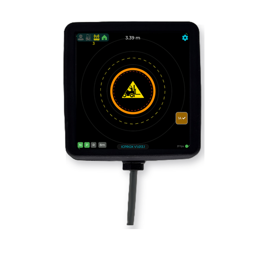
With one antenna only the distance is available: the range to the nearest tag appears as a figure at the top, and the coloured rings indicate the active reduction level. A single antenna cannot determine direction.
With three antennas direction is added. Every detected tag appears as a marker in its place, with its identifier beneath it; a sector colours towards whatever is there — green while it stays uncritical, red as soon as the stop stage takes effect. The dashed rectangles are the configured zones: one for each reduction stage.
| On screen | Meaning |
|---|---|
| Yellow warning triangle in the middle | The vehicle itself |
| Thin circles | Distance rings |
| Marker with radio symbol and identifier | A detected tag — person, vehicle or AGV |
| Green sector | Something detected, no intervention yet |
| Red sector | The stop stage is active in that direction |
| Dashed rectangles | The configured zones per reduction stage |
| Bar at the top left | How many people, vehicles, anchors and building points are in range |
| N P R at the bottom left | The state of the three subsystems — see below |
| 1A / 3A on the right | How many antennas the control unit has found |
The tick next to 1A or 3A is the first thing to check during installation: if the figure is lower than the number fitted, one antenna is not reporting in.
The status display N · P · R
The three fields at the bottom left do not show what is currently switched, but whether the three subsystems are working.
| Field | Stands for |
|---|---|
| N | ICPROX-N — the infrastructure in the building |
| P | ICPROX-P — the vehicle equipment itself |
| R | ICPROX-CAM — the rear-area camera and visual warning devices |
The colour speaks the same language in all three:
| Colour | Meaning |
|---|---|
| Green | working correctly |
| Yellow or red | fault or error |
| Grey | not installed |
Grey therefore does not indicate a fault but a subsystem that is not fitted: a vehicle without a rear-area camera shows R in grey. A change from green to yellow or red, by contrast, indicates a fault in that subsystem.
The three reduction levels and the action matrix
ICPROX-P has three levels — green, yellow, red. What each level triggers is not hard-wired but set in a matrix: per source and level you define which of the four relays pull in and which signal tone sounds.
Five sources are available:
| Source | Belongs to | Detects |
|---|---|---|
| FF | ICPROX-P | vehicle – vehicle |
| FP | ICPROX-P | vehicle – person |
| FAGV | ICPROX-P | vehicle – AGV |
| ANT | ICPROX-N | the infrastructure: danger points, gates, zones |
| Rear area | Sensors | the ICPROX-CAM behind the vehicle |
That gives fifteen combinations, each assigned independently. An example assignment: source FP at red switches relays 1 and 2 (stop), source FF at red only relay 1 (speed limit), source ANT at yellow only the beacon relay.
This is configured through the web interface of the control unit or with the setup tool.
Getting started
- Mount the control unit and wire it to the 24 V system; assign the relays to warning, speed limitation and stop.
- Fit the antennas — one facing the main direction of travel, three for all-round detection — and enter their mounting positions.
- Hand out tags: personal tags for people, vehicle tags for vehicles without their own system.
- Set the three reduction levels to the vehicle's size, speed and braking distance.
- Verify each switching point in practice with a personal tag before releasing the vehicle.
Wiring, configuration, reduction levels and troubleshooting are described in full in the system description and in the individual manuals.
Downloads
- System description (HTML, English/German)
- Complete ICPROX manual (PDF, English)
- Gesamthandbuch (PDF, deutsch)
Note: People without a tag are not detected by the radio locating. ICPROX-P assists the driver but does not relieve them of their duty of care.