Difference between revisions of "DW1000 Tag"
From InCircuit
(→Software) |
|||
| Line 20: | Line 20: | ||
==Software== | ==Software== | ||
| − | The {{PAGENAME}} | + | The {{PAGENAME}} is shipped programmed with a closed source firmware based on the [[dw1000 advanced demo]] from our [[radino Library]]. |
| − | ''' | + | '''Extended functionality of the {{PAGENAME}} firmware''' |
| − | * | + | * The stm32 enters stopMode when there is no activity to save as much power as possible |
| − | + | ||
| − | + | ||
| − | + | ||
| − | ''' | + | '''Functionality contained in the [[dw1000 advanced demo]] |
| + | * USB used as configuration interface (wireless channel, transmit power) | ||
| + | * When USB power is detected, the measuring algorithm is paused | ||
| + | * Measure and transmit battery voltage | ||
| + | * When no movement is deteceted for 30 seconds the DW1000 is put to sleep and the stm32 goes to idle (checking every 2 seconds if there now is movement) | ||
| + | * While USB power is detected the LEDs flashing signals charge state of the battery (Green:>4.125V,Yellow:>3.8V,Red:<3.8V) | ||
| + | * A succesfull distance mesurement is signaled by a LED flash (Green:RSSI>-75dBm,Yellow:RSSI>-90dBm,Red:RSSI<-90dBm) | ||
| + | * While turned upside down the battery voltage level ist signaled on LED (Green:>4.0V,Green/Yellow:>3.75,Yellow:>3.5V,Yellow/Red:>3.25,Red:<3.25V) | ||
| + | |||
| + | |||
| + | '''Working with the firmware command mode''' | ||
* Connect the {{PAGENAME}} to your PC via USB | * Connect the {{PAGENAME}} to your PC via USB | ||
| Line 40: | Line 47: | ||
> | > | ||
| − | + | ||
'''Available commands:''' | '''Available commands:''' | ||
| Line 46: | Line 53: | ||
aYYYY | aYYYY | ||
| − | * | + | * Set address to 0xYYYY. This overides the ID set during production. (Vaild values: 0x0000 to 0xFFFF) |
cX | cX | ||
* set channel to X. (Valid values: 1,2,3,4,5,7) | * set channel to X. (Valid values: 1,2,3,4,5,7) | ||
| Line 52: | Line 59: | ||
* set tx power to YY.Z dB (Range 0 to 33.5 steps of 0.5) | * set tx power to YY.Z dB (Range 0 to 33.5 steps of 0.5) | ||
f | f | ||
| − | * Toggle execute measurements. The module communicates with the anchors and prints out results. | + | * Toggle execute measurements. The module communicates with the anchors and prints out results even when powered by USB. |
r | r | ||
* reload last stored values from EEPROM | * reload last stored values from EEPROM | ||
| Line 58: | Line 65: | ||
* store current configuration to EEPROM (The F option is not stored and reset on USB disconnect) | * store current configuration to EEPROM (The F option is not stored and reset on USB disconnect) | ||
| − | |||
==Downloads== | ==Downloads== | ||
Revision as of 13:24, 13 October 2017
Hardware
Tag for Ranging / RTLS applications with radino32 DW1000 Ultra Wide Band module.
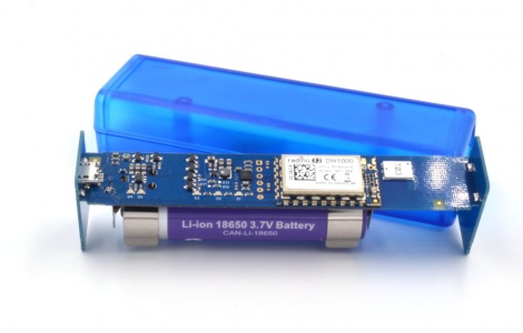
Features:
- radino32 DW1000 module
- Integrated UWB antenna
- Integrated USB-Li-ion loader for 18650 battery
- microUSB connector for battery loading
- Transparent enclosure
- Accelerometer, 3-Axis (Datasheet NXP MMA7660FC)
- 3 freely programmable LEDs
Software
The DW1000 Tag is shipped programmed with a closed source firmware based on the dw1000 advanced demo from our radino Library.
Extended functionality of the DW1000 Tag firmware
- The stm32 enters stopMode when there is no activity to save as much power as possible
Functionality contained in the dw1000 advanced demo
- USB used as configuration interface (wireless channel, transmit power)
- When USB power is detected, the measuring algorithm is paused
- Measure and transmit battery voltage
- When no movement is deteceted for 30 seconds the DW1000 is put to sleep and the stm32 goes to idle (checking every 2 seconds if there now is movement)
- While USB power is detected the LEDs flashing signals charge state of the battery (Green:>4.125V,Yellow:>3.8V,Red:<3.8V)
- A succesfull distance mesurement is signaled by a LED flash (Green:RSSI>-75dBm,Yellow:RSSI>-90dBm,Red:RSSI<-90dBm)
- While turned upside down the battery voltage level ist signaled on LED (Green:>4.0V,Green/Yellow:>3.75,Yellow:>3.5V,Yellow/Red:>3.25,Red:<3.25V)
Working with the firmware command mode
- Connect the DW1000 Tag to your PC via USB
- Start a terminal program (e.g. PuTTY, HTerm, Hyperterminal, ...) with 57600 baud and 8N1
- STM32 virtual com port driver need to be installed
- After opening the connection press <Enter> once to display the menu
A)ddr:0x1234  C)han:5  X)Str:27.5  R)eload  S)tore  F)orceMeas:N
>
Available commands:
All commands will be send by <Enter>.
aYYYY
- Set address to 0xYYYY. This overides the ID set during production. (Vaild values: 0x0000 to 0xFFFF)
cX
- set channel to X. (Valid values: 1,2,3,4,5,7)
xYYZ
- set tx power to YY.Z dB (Range 0 to 33.5 steps of 0.5)
f
- Toggle execute measurements. The module communicates with the anchors and prints out results even when powered by USB.
r
- reload last stored values from EEPROM
s
- store current configuration to EEPROM (The F option is not stored and reset on USB disconnect)
Downloads
- Datasheet: Datasheet DW1000 Tag
- Schematic: Schematic DW1000 Tag
- Arduino library for MMA7660FC: DigitalAccelerometer MMA7660FC or DigitalAccelerometer_MMA7660FC.zip
- How to import a .zip library to Arduino: arduino.cc
- How to import a .zip library to Arduino: arduino.cc