Difference between revisions of "Main Page"
(→radino radio modules) |
(→Avionics) |
||
| (15 intermediate revisions by one user not shown) | |||
| Line 16: | Line 16: | ||
== radino radio modules == | == radino radio modules == | ||
| − | <div style="width: | + | <div style="width: 450px; background: #1a1a1a; border: 1px solid #00e5ff; border-radius: 8px; padding: 15px; margin: 10px; float: left; box-shadow: 0 4px 10px rgba(0,0,0,0.3);"> |
<h3 style="color: #00e5ff; margin-top: 0; border-bottom: 1px solid #333; padding-bottom: 10px;">radino40 Series</h3> | <h3 style="color: #00e5ff; margin-top: 0; border-bottom: 1px solid #333; padding-bottom: 10px;">radino40 Series</h3> | ||
The latest generation based on Nordic nRF52840. High performance, UWB, 433/868MHz, BLE, Thread and Zigbee. | The latest generation based on Nordic nRF52840. High performance, UWB, 433/868MHz, BLE, Thread and Zigbee. | ||
| Line 58: | Line 58: | ||
</div> | </div> | ||
| − | <div style="width: | + | <div style="width: 450px; background: #1a1a1a; border: 1px solid #00e5ff; border-radius: 8px; padding: 15px; margin: 10px; float: left; box-shadow: 0 4px 10px rgba(0,0,0,0.3);"> |
<h3 style="color: #00e5ff; margin-top: 0; border-bottom: 1px solid #333; padding-bottom: 10px;">radino32 Series</h3> | <h3 style="color: #00e5ff; margin-top: 0; border-bottom: 1px solid #333; padding-bottom: 10px;">radino32 Series</h3> | ||
The powerful 32-bit platform based on STM32L1. Versatile wireless options for UWB, 433/868MHz, LoRa and WiFi. | The powerful 32-bit platform based on STM32L1. Versatile wireless options for UWB, 433/868MHz, LoRa and WiFi. | ||
| Line 95: | Line 95: | ||
</div> | </div> | ||
| − | + | <div style="clear: both;"></div> | |
| − | <div style=" | + | |
| − | + | ||
| − | + | == [[ICnova CPU Modules]] == | |
| − | + | ||
| − | + | ||
| − | + | ||
| − | + | ||
| − | + | ||
| − | + | ||
| − | + | ||
| − | + | ||
| − | + | ||
| − | + | ||
| − | + | <div style="width: 900px; background: #1a1a1a; border: 1px solid #00e5ff; border-radius: 8px; padding: 20px; margin: 10px; float: left; box-shadow: 0 4px 10px rgba(0,0,0,0.3); color: #eee;"> | |
| − | + | <h3 style="color: #00e5ff; margin-top: 0; border-bottom: 1px solid #333; padding-bottom: 10px;">ICnova CPU-Modules</h3> | |
| − | <h3 style="color: #00e5ff; margin-top: 0; border-bottom: 1px solid #333; padding-bottom: 10px;"> | + | |
| − | + | Here you can find all ICnova CPU-Modules which are offered by [https://www.in-circuit.de/product-category/icnova/icnova_cpu/ In-Circuit]. | |
| − | + | ||
| − | + | Basicly all our ICnova modules feature: | |
| − | + | 10/100MBit Ethernet PHY, USB Host/USB Device, SDC, TFT/Touch Display connections, multiple UARTS and GPIOS | |
| − | + | ||
| − | + | {| class="wikitable" style="width: 100%; background-color: #222; color: #eee; border: 1px solid #333; border-collapse: collapse; margin-top: 15px; font-size: 0.9em;" | |
| − | + | |- style="background-color: #1a1a1a; color: #00e5ff; text-align: left;" | |
| + | ! style="padding: 10px; border: 1px solid #333;" | CPU Module | ||
| + | ! style="padding: 10px; border: 1px solid #333;" | Image | ||
| + | ! style="padding: 10px; border: 1px solid #333;" | Compatible ADB | ||
| + | ! style="padding: 10px; border: 1px solid #333;" | ADB Image | ||
| + | ! style="padding: 10px; border: 1px solid #333;" | Form Factor / Features | ||
| + | ! style="padding: 10px; border: 1px solid #333;" | Status | ||
| + | |- | ||
| + | | style="padding: 8px; border: 1px solid #333;" nowrap | [[ICnova A20 SODIMM]] | ||
| + | | style="padding: 5px; border: 1px solid #333; text-align: center;" | [[File:901.244B005 45 1000 s.png|80px]] | ||
| + | | style="padding: 8px; border: 1px solid #333;" nowrap | [[ICnova ADB4006]] | ||
| + | | style="padding: 5px; border: 1px solid #333; text-align: center;" | [[File:901.318 45 1000 s.png|80px]] | ||
| + | | style="padding: 8px; border: 1px solid #333;" | SODIMM 200, ARM Dual CORTEX-A7, 1GHz, 1GB RAM, LVDS, HDMI, SATA | ||
| + | | style="padding: 8px; border: 1px solid #333; color: #00ff00; text-align: center;" | Active | ||
| + | |- | ||
| + | | style="padding: 8px; border: 1px solid #333;" nowrap | [[ICnova SAM9G45 SODIMM]] | ||
| + | | style="padding: 5px; border: 1px solid #333; text-align: center;" | [[File:901.227C_45_1000_s.png|80px]] | ||
| + | | style="padding: 8px; border: 1px solid #333;" nowrap | [[ICnova ADB4004]] | ||
| + | | style="padding: 5px; border: 1px solid #333; text-align: center;" | [[File:901.082_top_1000_s.png|80px]] | ||
| + | | style="padding: 8px; border: 1px solid #333;" | SODIMM 200, Atmel ARM9, 400MHz, 128MB RAM, 8MB NOR, 256MB NAND | ||
| + | | style="padding: 8px; border: 1px solid #333; color: #00ff00; text-align: center;" | Active | ||
| + | |- | ||
| + | | style="padding: 8px; border: 1px solid #333;" nowrap | [[ICnova SAM9G45 OEM]] | ||
| + | | style="padding: 5px; border: 1px solid #333; text-align: center;" | [[File:901.182B_45_1000_s.png|80px]] | ||
| + | | style="padding: 8px; border: 1px solid #333;" nowrap | [[ICnova ADB1000]] | ||
| + | | style="padding: 5px; border: 1px solid #333; text-align: center;" | [[File:901.133C_45_1000_s.png|80px]] | ||
| + | | style="padding: 8px; border: 1px solid #333;" | ICnova OEM (40x35mm), Atmel ARM9, 400MHz, 128MB RAM, 256MB NAND | ||
| + | | style="padding: 8px; border: 1px solid #333; color: #00ff00; text-align: center;" | Active | ||
|} | |} | ||
| + | |||
| + | <p style="font-size: 0.85em; color: #aaa; margin-top: 15px;"> | ||
| + | For information about legacy modules please consult [[Legacy products#ICnova CPU-Modules|legacy products]]. For BSPs visit the [[Downloads]] page. | ||
| + | </p> | ||
</div> | </div> | ||
| + | <div style="clear: both;"></div> | ||
== [[Avionics]] == | == [[Avionics]] == | ||
| − | <div style="width: | + | <div style="width: 900px; background: #1a1a1a; border: 1px solid #00e5ff; border-radius: 8px; padding: 15px; margin: 10px; float: left; box-shadow: 0 4px 10px rgba(0,0,0,0.3);"> |
| − | <h3 style="color: #00e5ff; margin-top: 0; border-bottom: 1px solid #333; padding-bottom: 10px;">ICfly Aviation Systems</h3> | + | <h3 style="color: #00e5ff; margin-top: 0; border-bottom: 1px solid #333; padding-bottom: 10px;">[[Avionics|ICfly Aviation Systems]]</h3> |
We offer several products that improve your in-flight experience. | We offer several products that improve your in-flight experience. | ||
{| class="wikitable" style="width: 100%; background-color: #222; color: #eee; border: 1px solid #333; border-collapse: collapse; margin-top: 20px;" | {| class="wikitable" style="width: 100%; background-color: #222; color: #eee; border: 1px solid #333; border-collapse: collapse; margin-top: 20px;" | ||
| Line 166: | Line 186: | ||
</div> | </div> | ||
| − | <div style="width: | + | <div style="clear: both;"></div> |
| + | |||
| + | == [[Programmer / Interface]] == | ||
| + | <div style="width: 450px; background: #1a1a1a; border: 1px solid #00e5ff; border-radius: 8px; padding: 15px; margin: 10px; float: left; box-shadow: 0 4px 10px rgba(0,0,0,0.3);"> | ||
<h3 style="color: #00e5ff; margin-top: 0; border-bottom: 1px solid #333; padding-bottom: 10px;">Programmer/Debugger</h3> | <h3 style="color: #00e5ff; margin-top: 0; border-bottom: 1px solid #333; padding-bottom: 10px;">Programmer/Debugger</h3> | ||
We offer several products that improve your in-flight experience. | We offer several products that improve your in-flight experience. | ||
| Line 192: | Line 215: | ||
</div> | </div> | ||
| − | <div style="width: | + | <div style="width: 450px; background: #1a1a1a; border: 1px solid #00e5ff; border-radius: 8px; padding: 15px; margin: 10px; float: left; box-shadow: 0 4px 10px rgba(0,0,0,0.3);"> |
<h3 style="color: #00e5ff; margin-top: 0; border-bottom: 1px solid #333; padding-bottom: 10px;">Interface Modules</h3> | <h3 style="color: #00e5ff; margin-top: 0; border-bottom: 1px solid #333; padding-bottom: 10px;">Interface Modules</h3> | ||
Reliable bridges and adapters for industrial communication and debugging. | Reliable bridges and adapters for industrial communication and debugging. | ||
| Line 204: | Line 227: | ||
|- | |- | ||
| style="padding: 8px; border: 1px solid #333;" | [[Interface Modules#USB UART Bridge ISO | USB UART Bridge ISO]] | | style="padding: 8px; border: 1px solid #333;" | [[Interface Modules#USB UART Bridge ISO | USB UART Bridge ISO]] | ||
| − | | style="padding: 5px; border: 1px solid #333; text-align: center;" | [[File:USB-UART-Brdige_ISO_45_640.jpg| | + | | style="padding: 5px; border: 1px solid #333; text-align: center;" | [[File:USB-UART-Brdige_ISO_45_640.jpg|x40px]] |
| style="padding: 8px; border: 1px solid #333;" | Optical UART Isolator, max 1Mbit | | style="padding: 8px; border: 1px solid #333;" | Optical UART Isolator, max 1Mbit | ||
| style="padding: 8px; border: 1px solid #333; color: #00ff00;" | Active | | style="padding: 8px; border: 1px solid #333; color: #00ff00;" | Active | ||
|- | |- | ||
| style="padding: 8px; border: 1px solid #333;" | [[Interface Modules#USB-B UART Bridge CP2102 | USB-B UART Bridge CP2102]] | | style="padding: 8px; border: 1px solid #333;" | [[Interface Modules#USB-B UART Bridge CP2102 | USB-B UART Bridge CP2102]] | ||
| − | | style="padding: 5px; border: 1px solid #333; text-align: center;" | [[File:USB-B UART Bridge.jpeg| | + | | style="padding: 5px; border: 1px solid #333; text-align: center;" | [[File:USB-B UART Bridge.jpeg|x40px]] |
| style="padding: 8px; border: 1px solid #333;" | USB-B to TTL UART bridge | | style="padding: 8px; border: 1px solid #333;" | USB-B to TTL UART bridge | ||
| style="padding: 8px; border: 1px solid #333; color: #00ff00;" | Active | | style="padding: 8px; border: 1px solid #333; color: #00ff00;" | Active | ||
|- | |- | ||
| style="padding: 8px; border: 1px solid #333;" | [[Interface Modules#USB-A UART Bridge CP2102 | USB-A UART Bridge CP2102]] | | style="padding: 8px; border: 1px solid #333;" | [[Interface Modules#USB-A UART Bridge CP2102 | USB-A UART Bridge CP2102]] | ||
| − | | style="padding: 5px; border: 1px solid #333; text-align: center;" | [[File:USB-A UART Bridge.jpeg| | + | | style="padding: 5px; border: 1px solid #333; text-align: center;" | [[File:USB-A UART Bridge.jpeg|x40px]] |
| style="padding: 8px; border: 1px solid #333;" | USB-A to TTL UART bridge (CP2102) | | style="padding: 8px; border: 1px solid #333;" | USB-A to TTL UART bridge (CP2102) | ||
| style="padding: 8px; border: 1px solid #333; color: #00ff00;" | Active | | style="padding: 8px; border: 1px solid #333; color: #00ff00;" | Active | ||
|- | |- | ||
| style="padding: 8px; border: 1px solid #333;" | [[Interface Modules#USB-A UART Bridge CP2104 | USB-A UART Bridge CP2104]] | | style="padding: 8px; border: 1px solid #333;" | [[Interface Modules#USB-A UART Bridge CP2104 | USB-A UART Bridge CP2104]] | ||
| − | | style="padding: 5px; border: 1px solid #333; text-align: center;" | [[File:CP2104_45.jpg| | + | | style="padding: 5px; border: 1px solid #333; text-align: center;" | [[File:CP2104_45.jpg|x40px]] |
| style="padding: 8px; border: 1px solid #333;" | USB-A to TTL UART bridge (CP2104) | | style="padding: 8px; border: 1px solid #333;" | USB-A to TTL UART bridge (CP2104) | ||
| style="padding: 8px; border: 1px solid #333; color: #00ff00;" | Active | | style="padding: 8px; border: 1px solid #333; color: #00ff00;" | Active | ||
|- | |- | ||
| style="padding: 8px; border: 1px solid #333;" | [[Interface Modules#USB-RS485-Bridge | USB-RS485-Bridge]] | | style="padding: 8px; border: 1px solid #333;" | [[Interface Modules#USB-RS485-Bridge | USB-RS485-Bridge]] | ||
| − | | style="padding: 5px; border: 1px solid #333; text-align: center;" | [[File:USB-RS485-Bridge.jpeg| | + | | style="padding: 5px; border: 1px solid #333; text-align: center;" | [[File:USB-RS485-Bridge.jpeg|x40px]] |
| style="padding: 8px; border: 1px solid #333;" | USB to RS485 industrial bridge | | style="padding: 8px; border: 1px solid #333;" | USB to RS485 industrial bridge | ||
| style="padding: 8px; border: 1px solid #333; color: #00ff00;" | Active | | style="padding: 8px; border: 1px solid #333; color: #00ff00;" | Active | ||
|- | |- | ||
| style="padding: 8px; border: 1px solid #333;" | [[Interface Modules#USB-B-RS232_Bridge | USB-B-RS232 Bridge]] | | style="padding: 8px; border: 1px solid #333;" | [[Interface Modules#USB-B-RS232_Bridge | USB-B-RS232 Bridge]] | ||
| − | | style="padding: 5px; border: 1px solid #333; text-align: center;" | [[File:USB-B-RS232_Bridge_45.jpg| | + | | style="padding: 5px; border: 1px solid #333; text-align: center;" | [[File:USB-B-RS232_Bridge_45.jpg|x40px]] |
| style="padding: 8px; border: 1px solid #333;" | USB-B to RS232 adapter | | style="padding: 8px; border: 1px solid #333;" | USB-B to RS232 adapter | ||
| style="padding: 8px; border: 1px solid #333; color: #00ff00;" | Active | | style="padding: 8px; border: 1px solid #333; color: #00ff00;" | Active | ||
|- | |- | ||
| style="padding: 8px; border: 1px solid #333;" | [[Interface Modules#RS232(DTE)-UART-Bridge | RS232(DTE)-UART-Bridge]] | | style="padding: 8px; border: 1px solid #333;" | [[Interface Modules#RS232(DTE)-UART-Bridge | RS232(DTE)-UART-Bridge]] | ||
| − | | style="padding: 5px; border: 1px solid #333; text-align: center;" | [[File:RS232-DTE-Bridge_45.jpg| | + | | style="padding: 5px; border: 1px solid #333; text-align: center;" | [[File:RS232-DTE-Bridge_45.jpg|x40px]] |
| style="padding: 8px; border: 1px solid #333;" | RS232 DTE to UART level shifter | | style="padding: 8px; border: 1px solid #333;" | RS232 DTE to UART level shifter | ||
| style="padding: 8px; border: 1px solid #333; color: #00ff00;" | Active | | style="padding: 8px; border: 1px solid #333; color: #00ff00;" | Active | ||
|- | |- | ||
| style="padding: 8px; border: 1px solid #333;" | [[Interface Modules#RS232(DCE)-UART-Bridge | RS232(DCE)-UART-Bridge]] | | style="padding: 8px; border: 1px solid #333;" | [[Interface Modules#RS232(DCE)-UART-Bridge | RS232(DCE)-UART-Bridge]] | ||
| − | | style="padding: 5px; border: 1px solid #333; text-align: center;" | [[File:RS232-DCE-Bridge_45.jpg| | + | | style="padding: 5px; border: 1px solid #333; text-align: center;" | [[File:RS232-DCE-Bridge_45.jpg|x40px]] |
| style="padding: 8px; border: 1px solid #333;" | RS232 DCE to UART level shifter | | style="padding: 8px; border: 1px solid #333;" | RS232 DCE to UART level shifter | ||
| style="padding: 8px; border: 1px solid #333; color: #00ff00;" | Active | | style="padding: 8px; border: 1px solid #333; color: #00ff00;" | Active | ||
| Line 247: | Line 270: | ||
</div> | </div> | ||
</div> | </div> | ||
| + | |||
| + | <div style="clear: both;"></div> | ||
== Production == | == Production == | ||
Latest revision as of 18:54, 24 February 2026
Contents |
Welcome to the In-Circuit Wiki In-Circuit provides development and manufacturing services of electronics for
- Radio applications with radio-modules, antenna-designs, ultra-low-power designs for Battery-powered applications or energy harvesting solutions
- Compact and energy-efficient embedded PC modules based on ARM and CORTEX architectures
Here different pages can be found, which describe all products that can be ordered at our online-shop.
We intend to expand these resources continuously. So if any questions arise, which are not yet answered here, please write us an E-mail.
To help you by looking for articles regarding to your product, we have grouped them into individual categories you can find in the sections below.
[edit] radino radio modules
radino40 Series
The latest generation based on Nordic nRF52840. High performance, UWB, 433/868MHz, BLE, Thread and Zigbee.
| Module | Image | Proposed Features | Status |
|---|---|---|---|
| radino40 | 
|
BT 5.0, Zigbee, Thread (Secondary radio from nRF only) | Active |
| radino40 DW1000 | 
|
Ultra-Wideband (UWB) for precise 10cm ranging, Channels 2-7 | Active |
| radino40 DW3000 | 
|
Ultra-Wideband (UWB) for precise 10cm ranging, Channels 5+9, FiRa | Active |
| radino40 CC1101 433 | 
|
Sub-GHz Radio (868MHz), high range, low power | Active |
| radino40 CC1101 868 | 
|
Sub-GHz Radio (868MHz), high range, low power | Active |
radino32 Series
The powerful 32-bit platform based on STM32L1. Versatile wireless options for UWB, 433/868MHz, LoRa and WiFi.
| Module | Image | Proposed Features | Status |
|---|---|---|---|
| radino32 DW1000 |
|
Ultra-Wideband (UWB) for precise 10cm ranging, Channels 2-7 | Active |
| radino32 CC1101 433 | 
|
Sub-GHz Radio (868MHz), high range, low power | Active |
| radino32 CC1101 868 |
|
Sub-GHz Radio (868MHz), high range, low power | Active |
| radino32 SX1272 | 
|
Sub-GHz Radio (868MHz), LoRa - long range, low power | Active |
[edit] ICnova CPU Modules
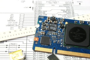
ICnova CPU-Modules
Here you can find all ICnova CPU-Modules which are offered by In-Circuit.
Basicly all our ICnova modules feature: 10/100MBit Ethernet PHY, USB Host/USB Device, SDC, TFT/Touch Display connections, multiple UARTS and GPIOS
| CPU Module | Image | Compatible ADB | ADB Image | Form Factor / Features | Status |
|---|---|---|---|---|---|
| ICnova A20 SODIMM | 
|
ICnova ADB4006 | 
|
SODIMM 200, ARM Dual CORTEX-A7, 1GHz, 1GB RAM, LVDS, HDMI, SATA | Active |
| ICnova SAM9G45 SODIMM | 
|
ICnova ADB4004 | 
|
SODIMM 200, Atmel ARM9, 400MHz, 128MB RAM, 8MB NOR, 256MB NAND | Active |
| ICnova SAM9G45 OEM | 
|
ICnova ADB1000 | 
|
ICnova OEM (40x35mm), Atmel ARM9, 400MHz, 128MB RAM, 256MB NAND | Active |
For information about legacy modules please consult legacy products. For BSPs visit the Downloads page.
[edit] Avionics
ICfly Aviation Systems
We offer several products that improve your in-flight experience.
| Device | Image | Description / Main features / Notes | Status |
|---|---|---|---|
| ICflyAHRSII | 
|
Altitude Heading Reference System Provides an artificial horizon. (Roll, Pitch, Magnetic Heading, Altitude, Airspeed, ...) |
Active |
| ICflyDisplay | 
|
Shows artificial horizon, engine data or traffic information on integrated transflective display |
Active |
| ICflyMotorbox 912 | 
|
Provides engine data for ICflyAHRSII and ICflyDisplay Power supply for ICflyBus |
Active |
| ICfly-TRX1500-Adapter | 
|
Connects your TRX-1500 Traffic Sensor with the ICfly Bus. |
Active |
[edit] Programmer / Interface
Programmer/Debugger
We offer several products that improve your in-flight experience.
| Device | Image | Description / Main features / Notes | Status |
|---|---|---|---|
| radino40 Programmer | 
|
Programmer for radino40 radio modules. Stand Alone field programmer. | Active |
| ICprog OpenOCD | 
|
OpenOCD JTAG Adapter | Active |
Interface Modules
Reliable bridges and adapters for industrial communication and debugging.
| Device | Image | Description | Status |
|---|---|---|---|
| USB UART Bridge ISO | |
Optical UART Isolator, max 1Mbit | Active |
| USB-B UART Bridge CP2102 | |
USB-B to TTL UART bridge | Active |
| USB-A UART Bridge CP2102 | |
USB-A to TTL UART bridge (CP2102) | Active |
| USB-A UART Bridge CP2104 | |
USB-A to TTL UART bridge (CP2104) | Active |
| USB-RS485-Bridge | |
USB to RS485 industrial bridge | Active |
| USB-B-RS232 Bridge | |
USB-B to RS232 adapter | Active |
| RS232(DTE)-UART-Bridge | |
RS232 DTE to UART level shifter | Active |
| RS232(DCE)-UART-Bridge | |
RS232 DCE to UART level shifter | Active |
[edit] Production
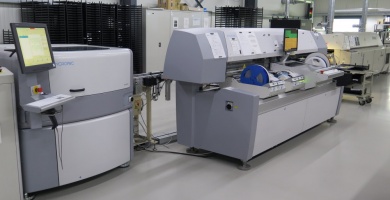
Format für Maschinendaten zur Lohnfertigung
Machine data format for job order production
[edit] HowTo
Flashing a new ZWIR4512 Firmware
[edit] Downloads
Any software can be found on the Downloads page
[edit] Legacy products
List of legacy products